New Scout Racing Lifters
$650.00 per set of 4 Lifters - 104 1/2 Degree Lobe
Centers
Now with "Needle Bearing Rollers"
I have been interested in the Indian valve train for quite some time now,
and from necessity, I had to design and build all new Scout cams, and lifters
for my Twin Enginned Bonneville LSR racer. I did a full years
research to find, and measure all sorts of Indian racing, and Bonneville cams to
get an understanding of what had been done in the past. I also contacted the
famous Bob Nichols to pick his brain, and archives in order to get a true
mechanical understanding of the Indian cam chest layout. After
many hours of banter with Bob, and alot of backward engineering, I discovered
how the Indian valve train really works. See my section on "Indian Valve
Train Revealed". Also, you should check out my "Indian Cam
Study" section where I have covered alot of information about
existing cam designs for the Chief, and Scout.
I would like to thank Bob Stark for donating a NOS set of Sport Scout
lifters, and the loan of several sets of his cams, and lifters for research.
After determining the exact geometry that I wanted to use for the lifters, I
made jigs to correctly setup parts in the cam chest. I cut the NOS lifters in
half, and placed the (2) halves into a special holding jig that placed the
pivoting end of the lifter in the correct position. Also, so that the push rod pad
would be at a precise 90 degree angle from the lifter pivot pin center at "mid-lift". I tack welded the (2) lifter cut halves together with TIG bronze.
After removing the lifter, I finish welded it, and then detailed the final
shape. I then took these lifters to Jim Chadwell (a highly experianced man who
does all the castings for Mike Breeding). Jim casts everything in 4140 "chrome
steel". This 4140 heat treats very well, in fact as good or better than a
forging. We discussed the areas where the lifters were inherently weak, and he
built them up with a wax layer, so that the new lifters would have some
additional meat where they were weak. After waxing-up the prototype lifters, he
made rubber molds, so he could then pour wax copies of them. The waxes are then
all grouped together as a tree, and then the whole assembly is dipped into a
special pourous plaster-like solution. Then it goes to the foundry to get the
pour done. As the molten steel is poured in, the wax burns out through the
pourous plaster layer, and the steel fills the exact void that was occupied with
the wax samples. There is always some shrinkage during cooling, and Jim built up
my prototype lifters with wax before making the rubber molds to account for this
shrinkage. My new lifter castings came out exactly like I wanted them to. They
look almost exactly like the originals, except that they have more material
where they need it for extra strength. They do end up just slightly heavier
(about 60 grams vs. 55 grams), but the extra strength is well worth it.
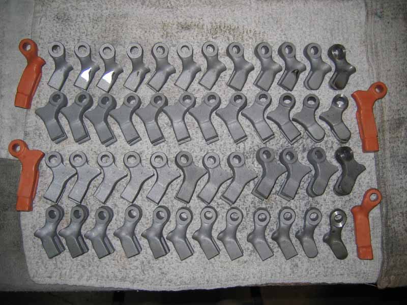
Here you can see the raw castings before machining, and (4) of the wax
samples.
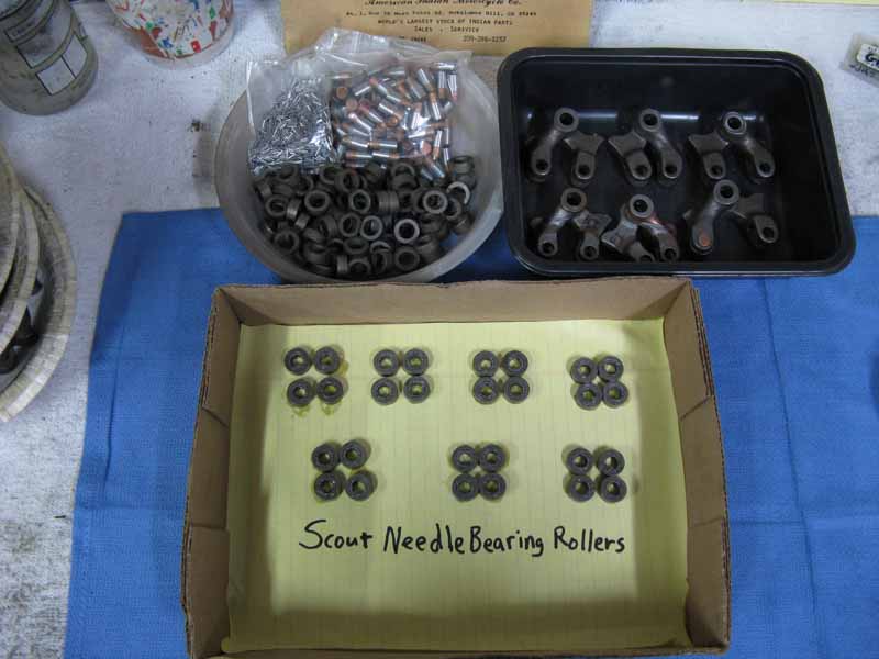
I decided to have needle bearing rollers made for my lifters, because the original style axle/roller combinations that are presently available from the vendors are inferior. They fail in about 2 hours of running time. They skid, and score the roller, and cam surfaces. My rollers were made from "52100 Bearing Grade Steel", which is used for roller bearings, and bearing races. But now my latest batch of lifter rollers are made from "S-5" shock resistant steel, with an increased OD from .625" up to .700" for more strength. They are precision ground, then heat treated all the way through to Rockwell 58! There are 24 high quality "American Made" needles used. This setup is working well. My axles are from Bob Stark or Jerry Greer's. These needle bearing rollers can endure much higher valve spring pressures before the roller would skid.
First I reamed the pivot holes for .375", and with a special holding
mandrel, I turned the pivot hole sides to a precise .500" width. I then made a
special holding jig to perform several machining operations. My jig allows me to
precisely grind the push rod pad arc in the correct shape, and place. I use the
same holding jig to mill the slot in the forked end where the roller lives, and
the jig is also used for precisely drilling, and reaming the roller axle holes.
The lifters are heat-treated to Rockwell 62 for good long term wear at the "Arched Pads", and the pivot pin hole.
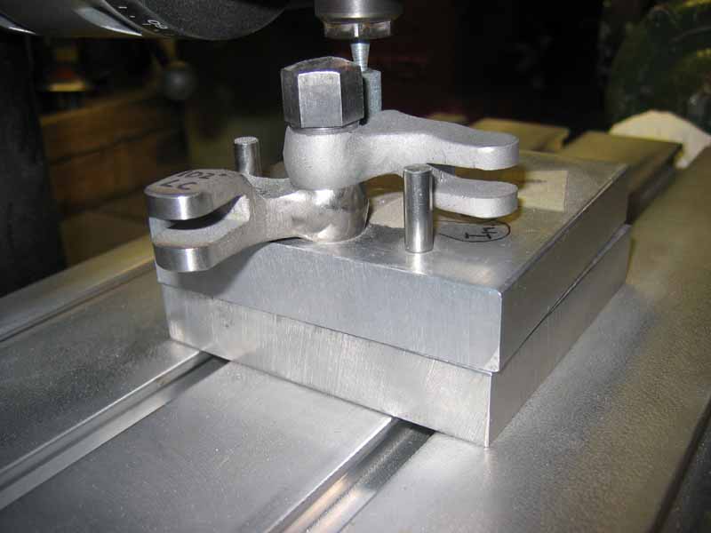
Here you can see my holding jig for grinding the push rod pad arc. I rotate
the top half of the jig into a rotating 3/8" grinding stone.
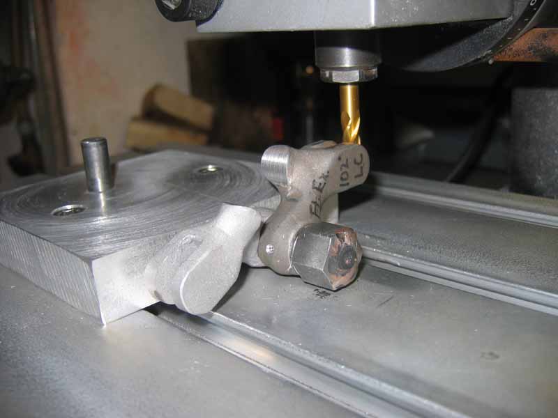
Here you can see the forked end being milled square for the rollers.
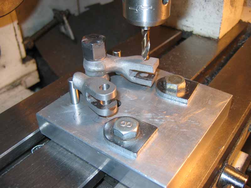
Here you can see the holding jig being used for drilling the roller axle
holes. First I use my prototypes to locate the exact position of the jig before
installing a casting for drilling.
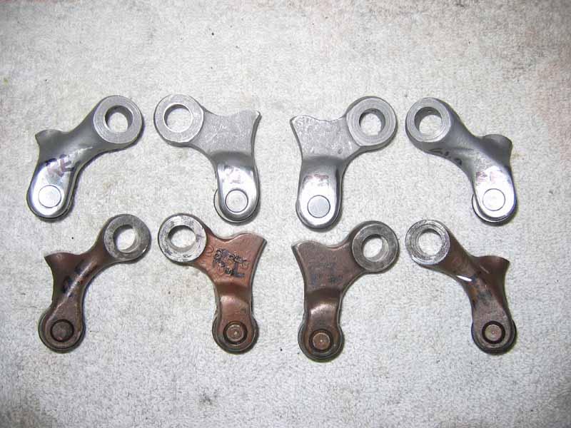
Here you can see my new lifters compared to original Sport Scout lifters.
Notice the extra strength added to the fork areas, as well as the main body on
the exhaust lifters. You can also see that the new lifters are shorter than the
standard lifters. They offer a new lobe center line of 104 1/2 degrees.

Here you can see the added width of the fork edges for added strength.
CONTACT INFORMATION:
James R. Mosher
(505) 466-7870